Implementation
Stroke Placement
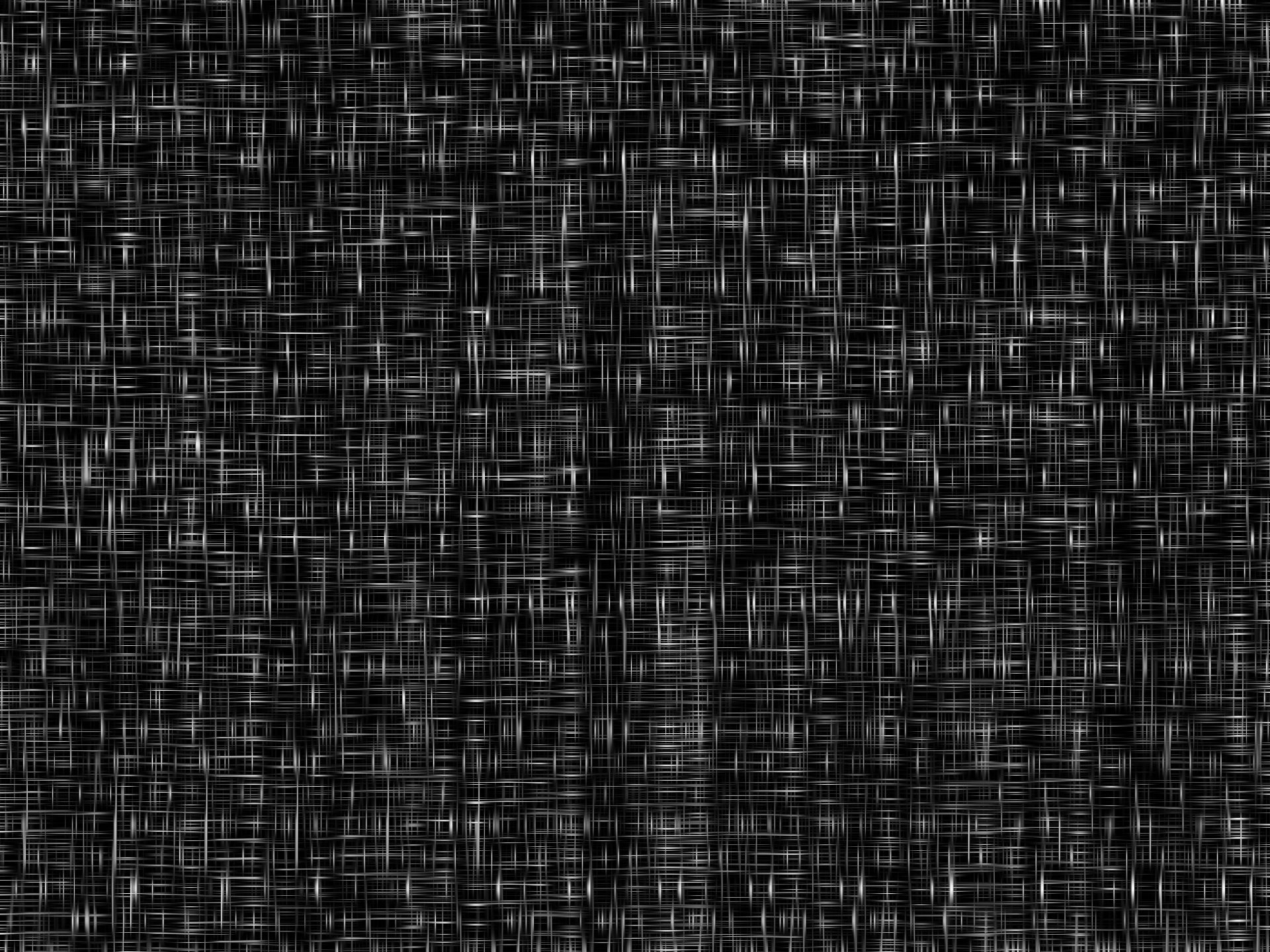
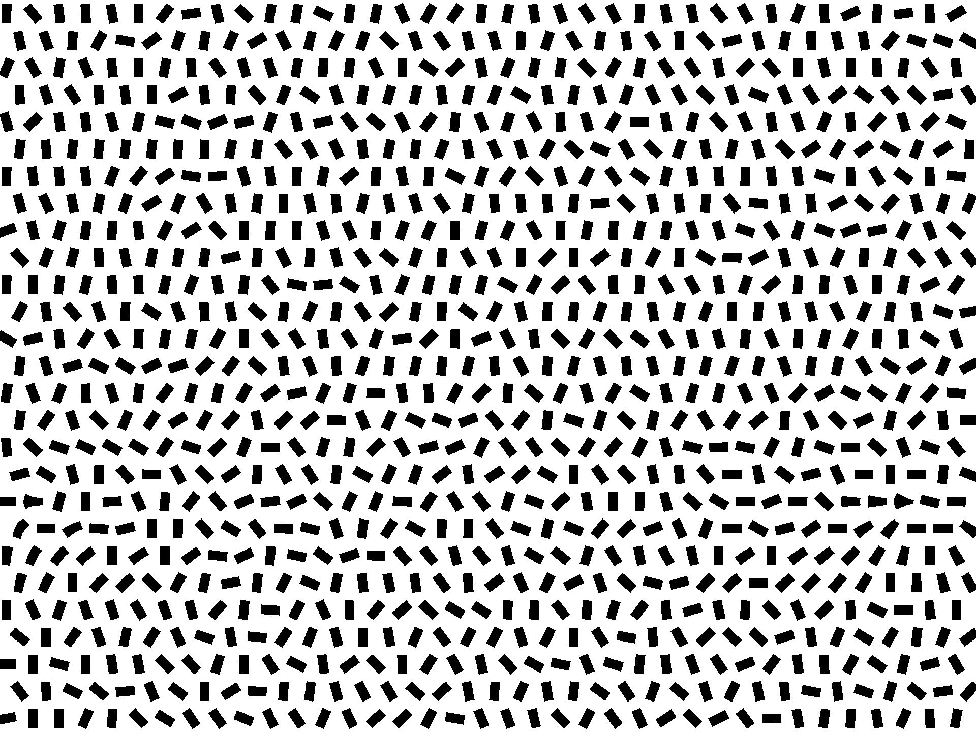
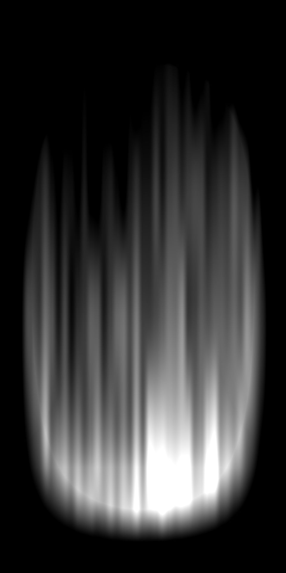
The system generates a procedural canvas texture by stretching noise fields in both X and Y directions, using a Max blend to simulate cross-noise fibers.
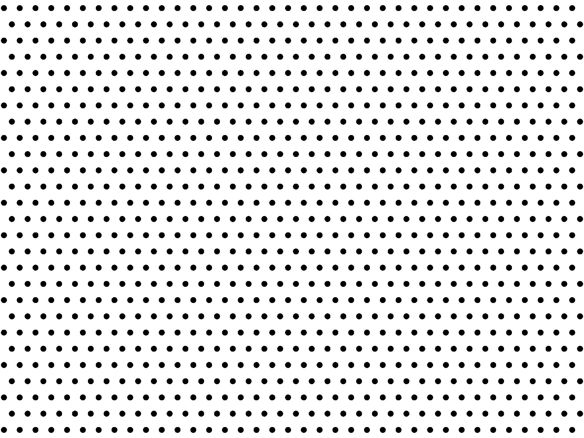
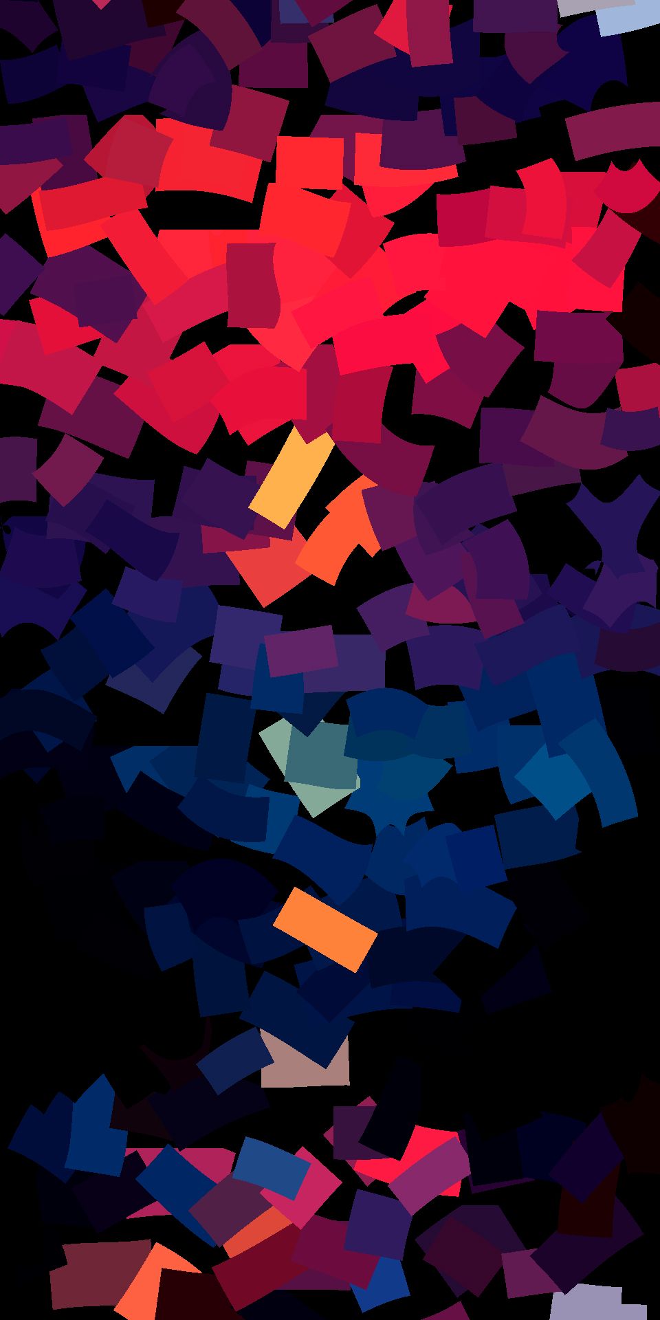
To organize the brush strokes, the source image is divided into a grid with an offset second row, forming a triangular pattern. For each grid cell, sampling coordinates are transformed from global UV space into the brush’s local space:
float2 pos = float2(dot(uv, n), dot(uv, t)) / float2(brushWidth, brushLength);
The stroke direction is determined by estimating the color gradient at the cell center using central difference: .
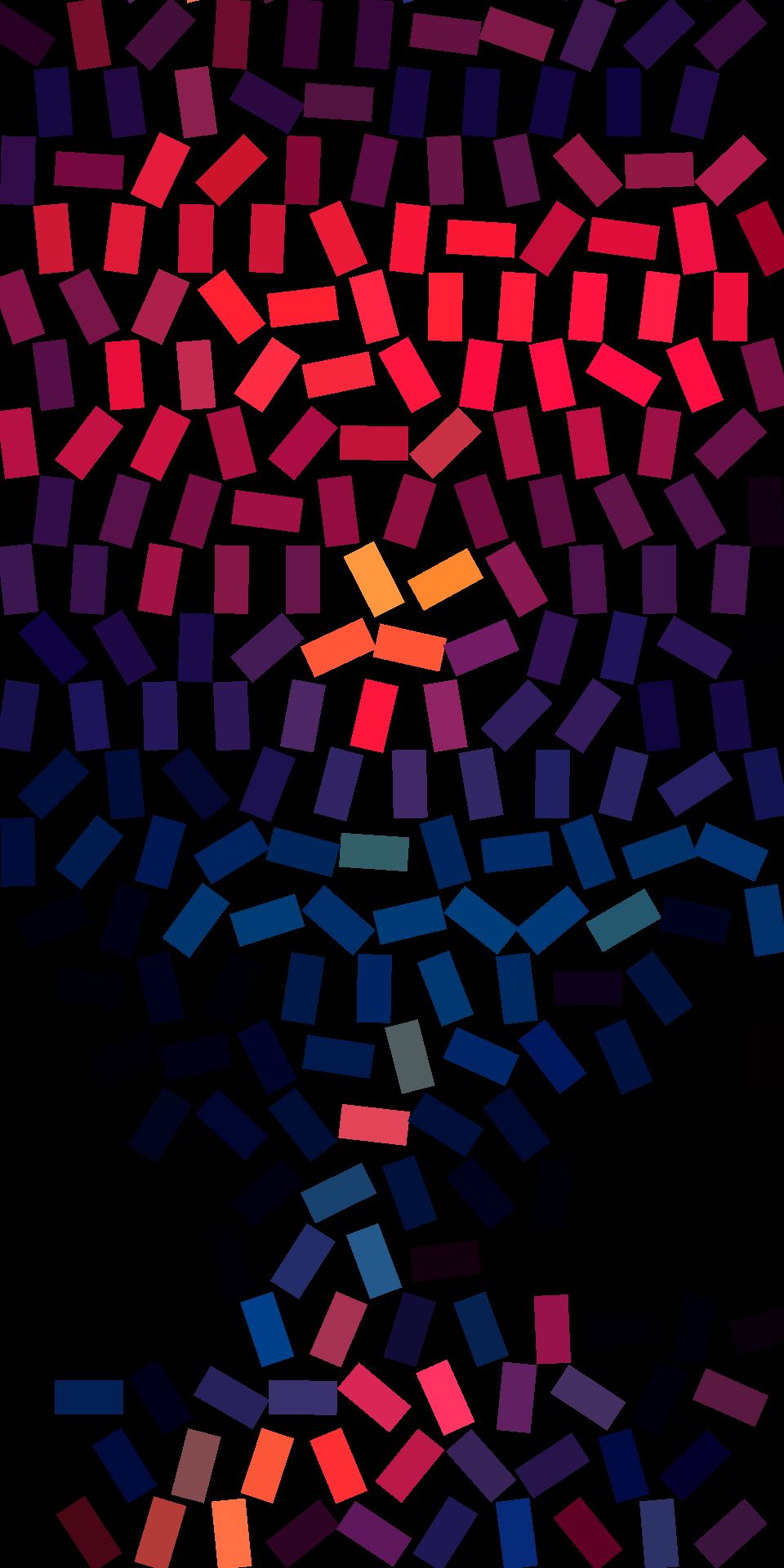
Stroke Variation
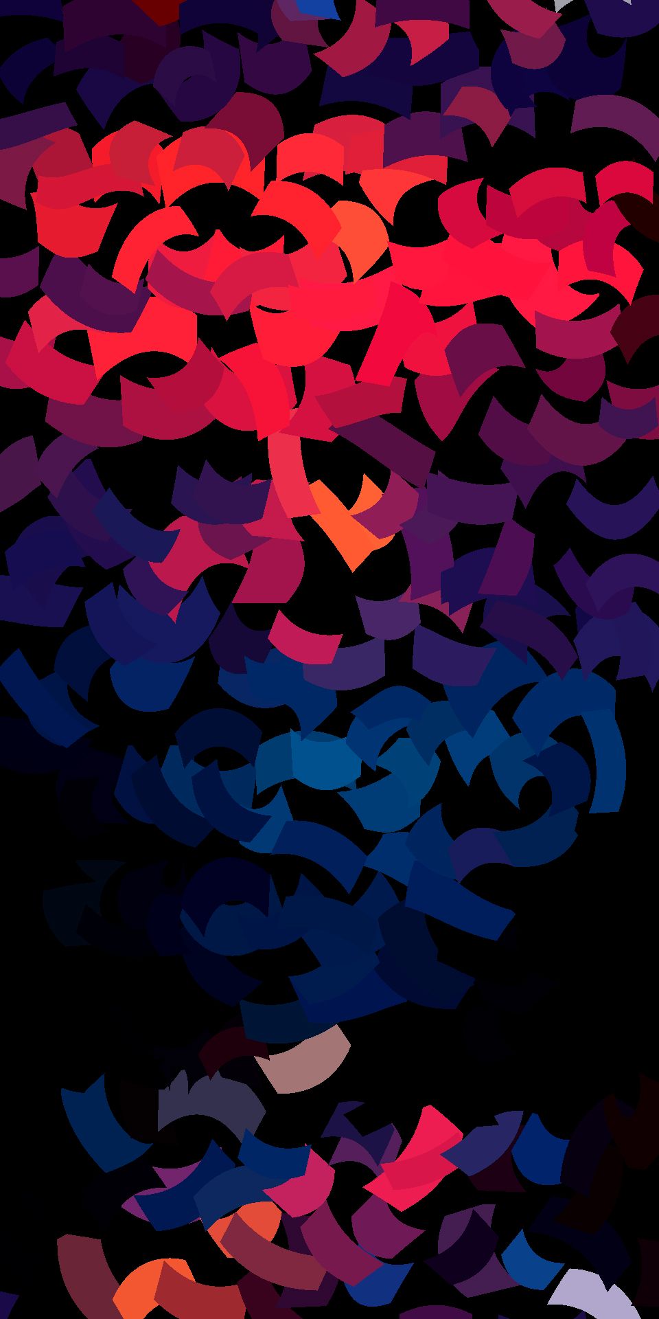
The implementation supports randomized brush positioning and stretching, stroke bending, and multi-layer stacking at varying grid scales to build visual complexity.
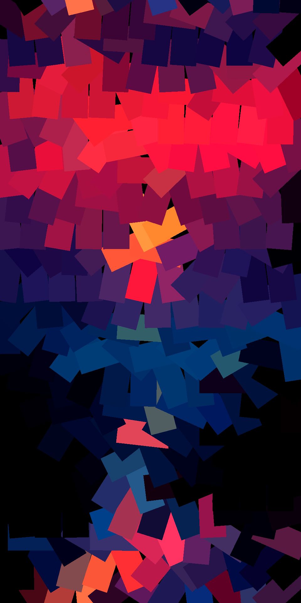
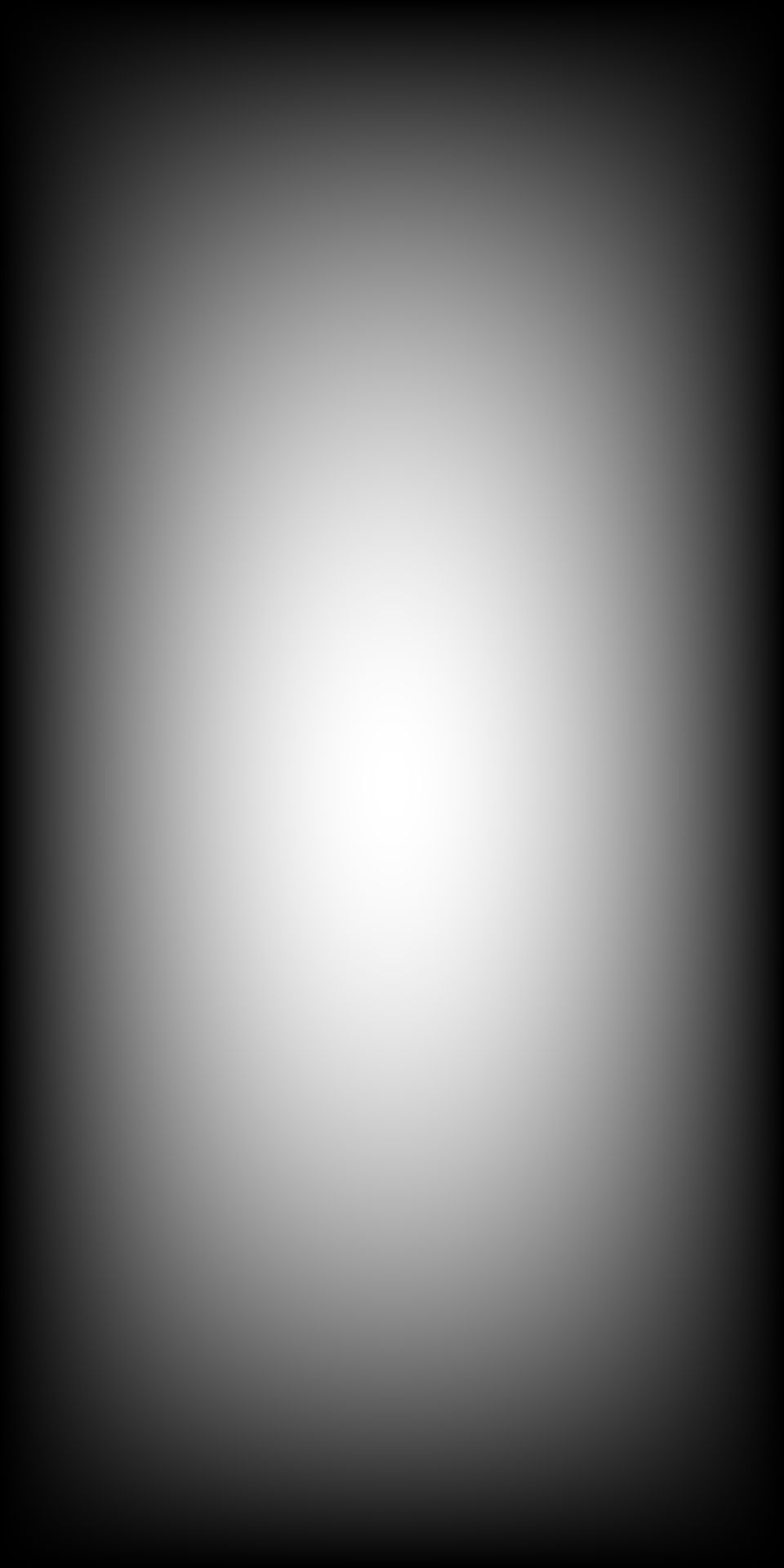
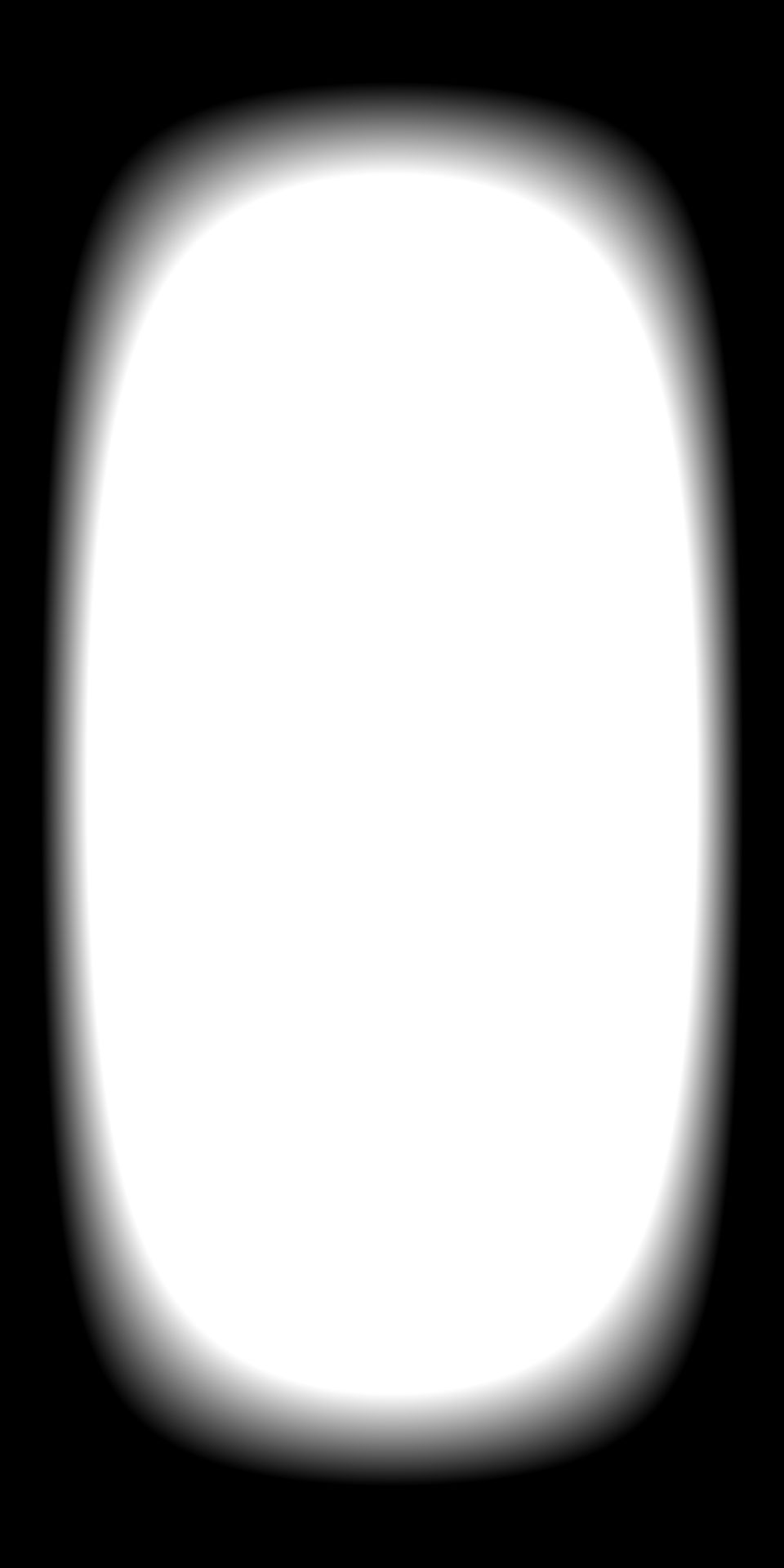
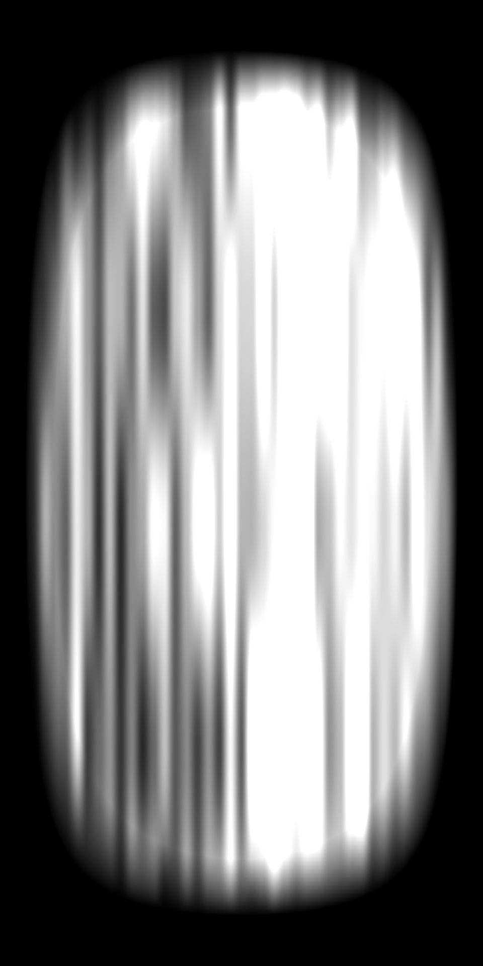
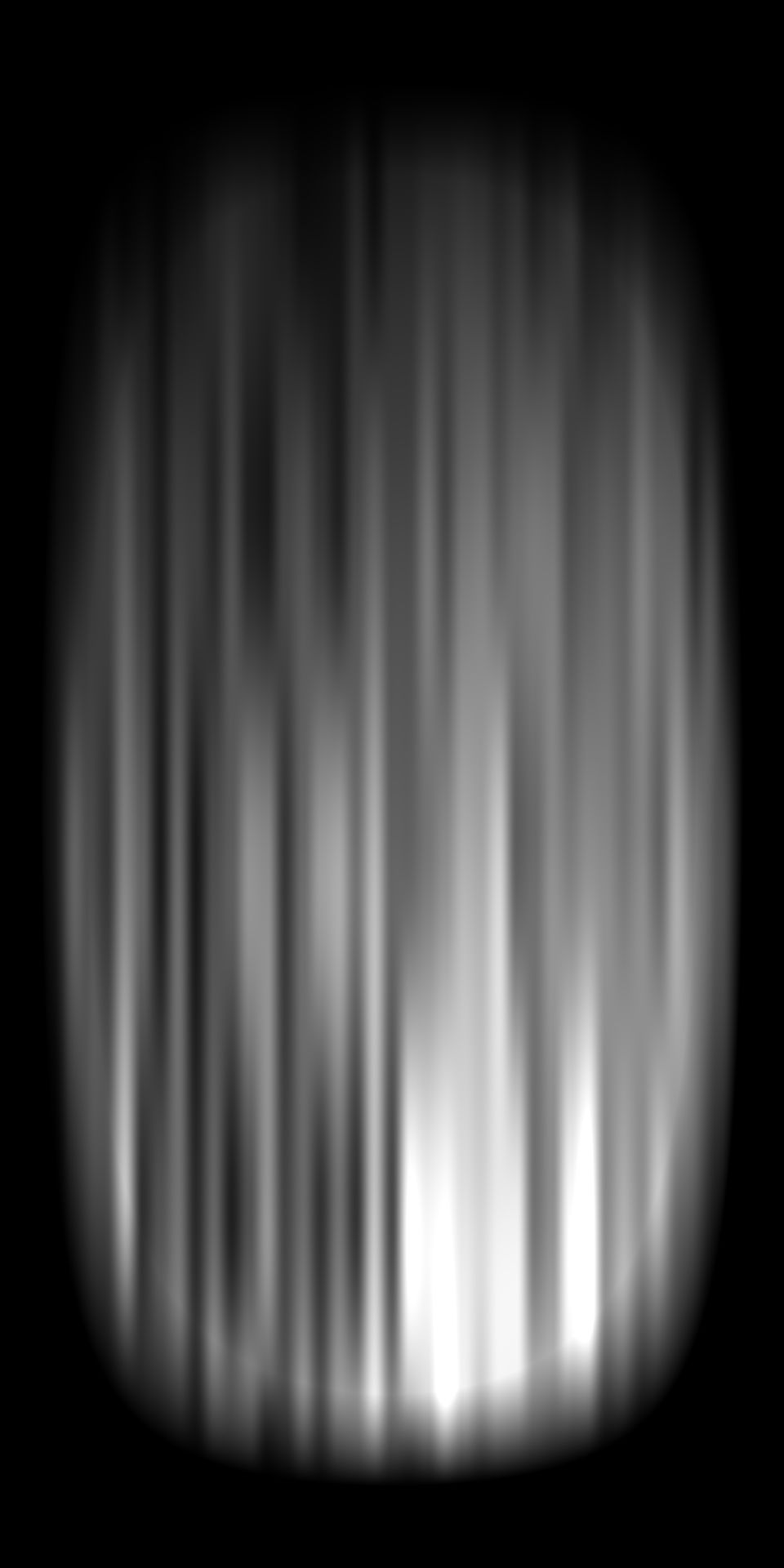
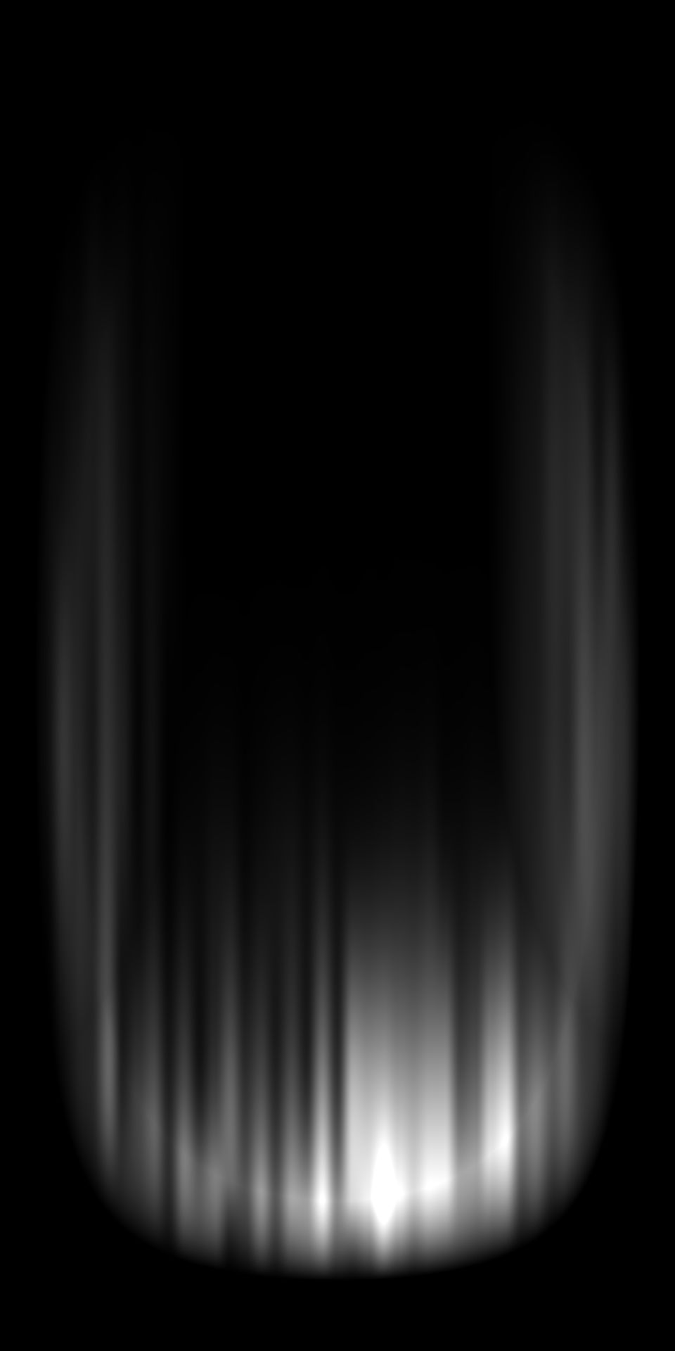
Procedural Brush Shaping
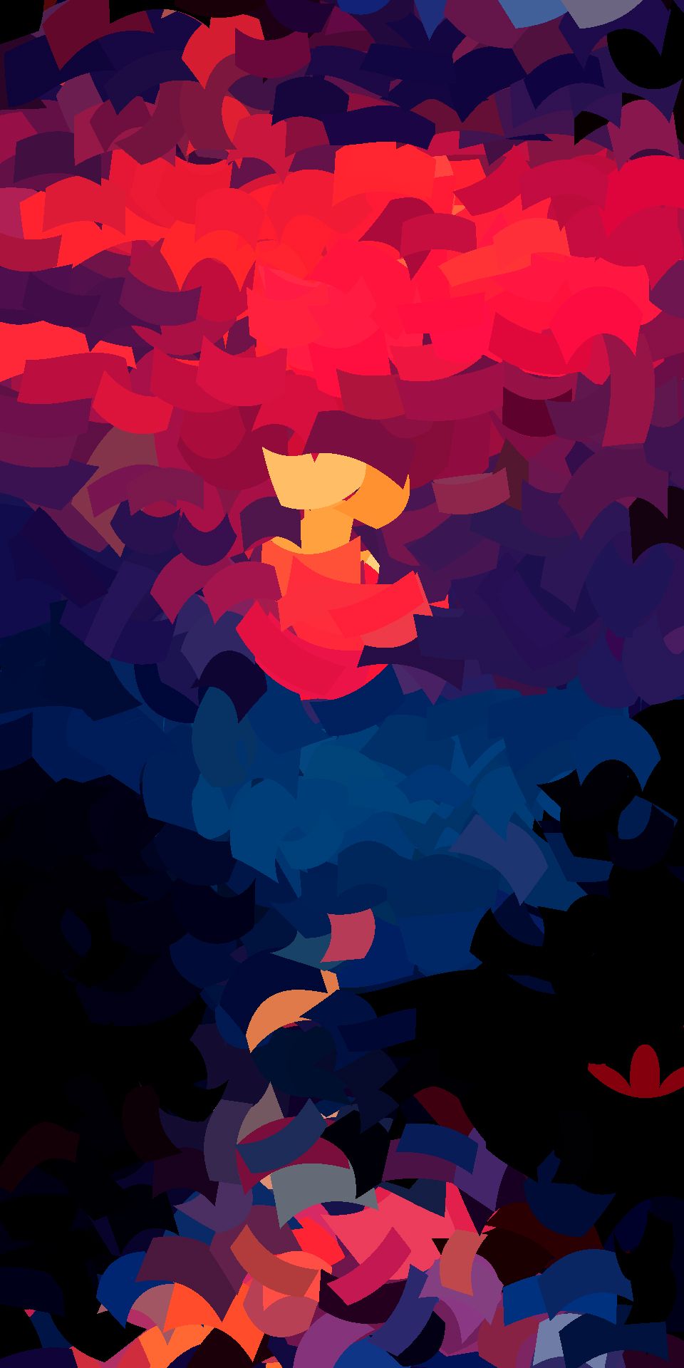
The images below illustrate the progressive shaping of the brush stroke through staged mathematical operations:
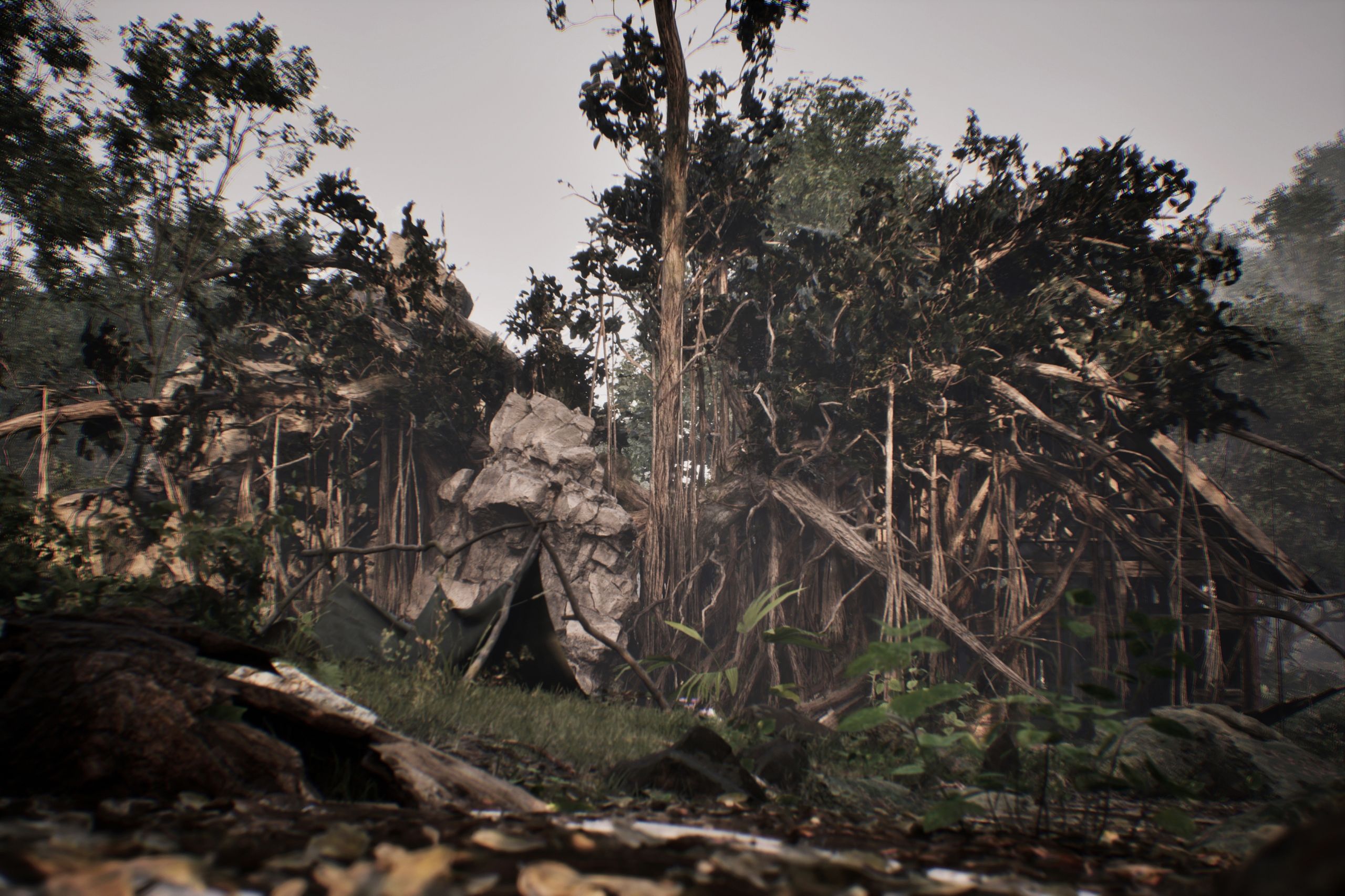
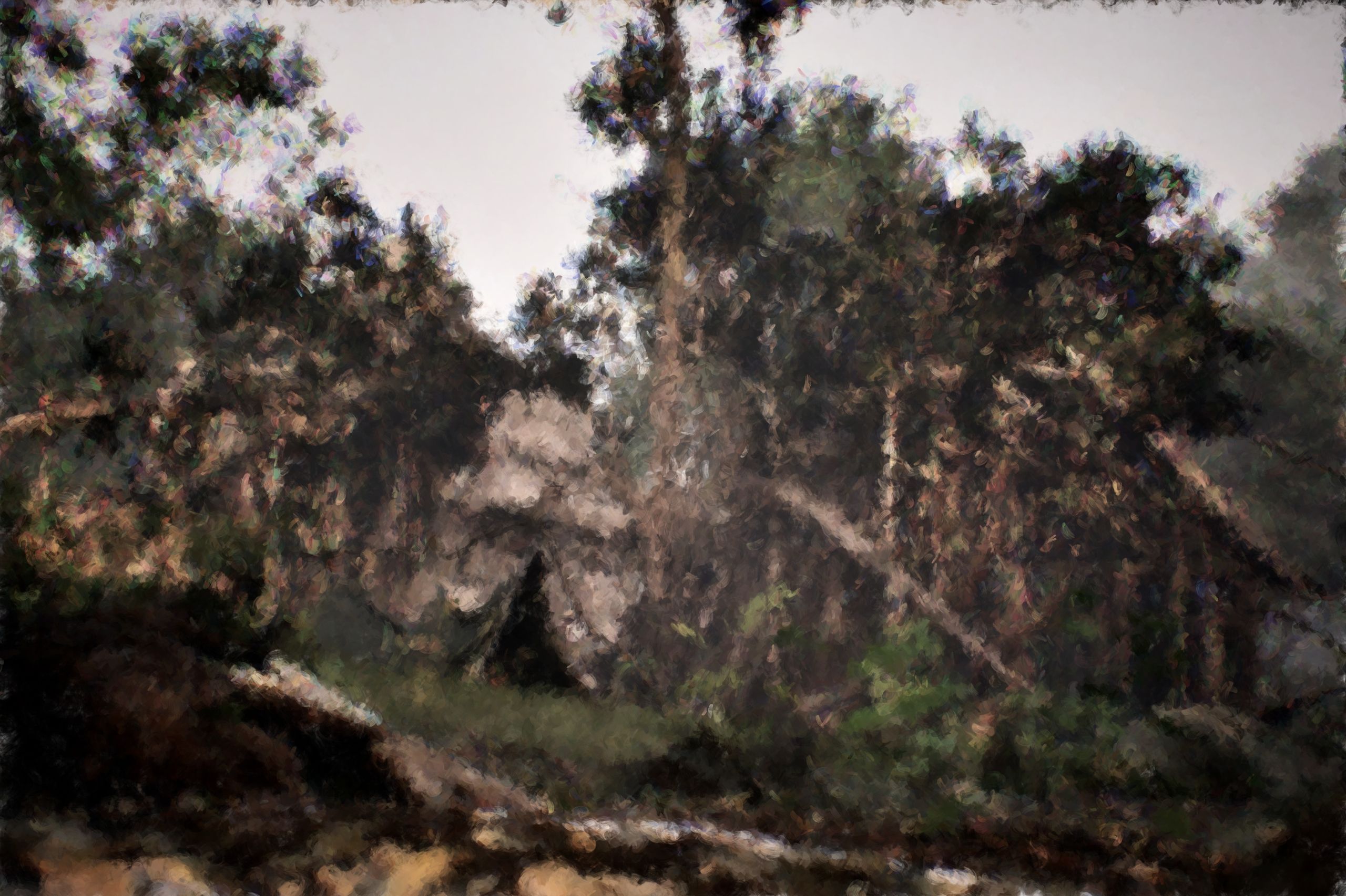
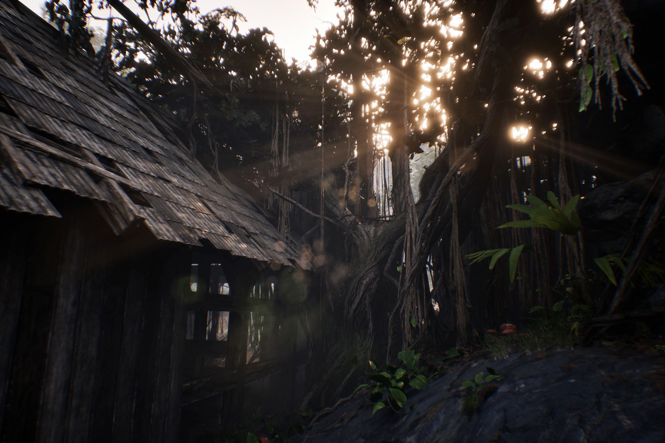
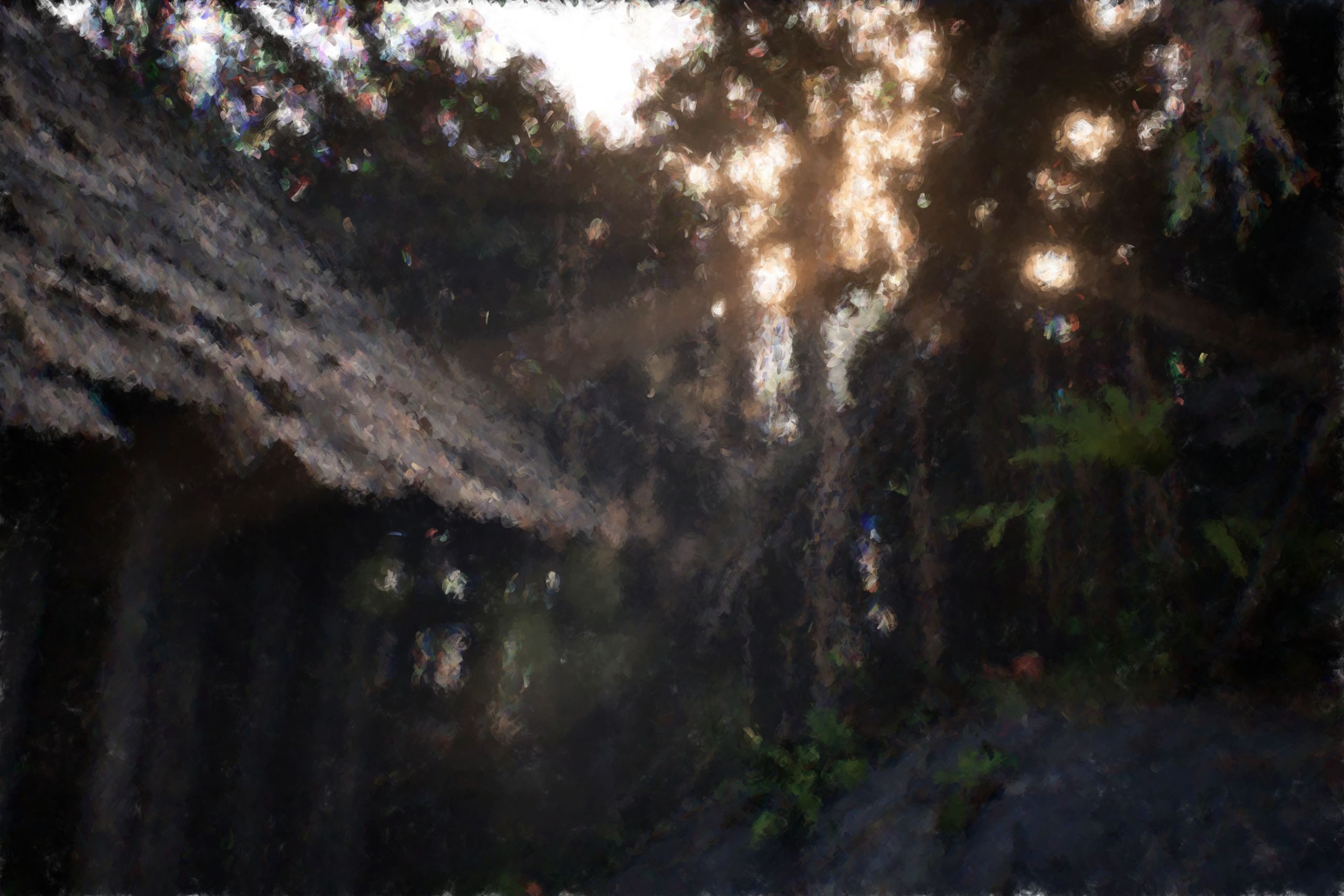
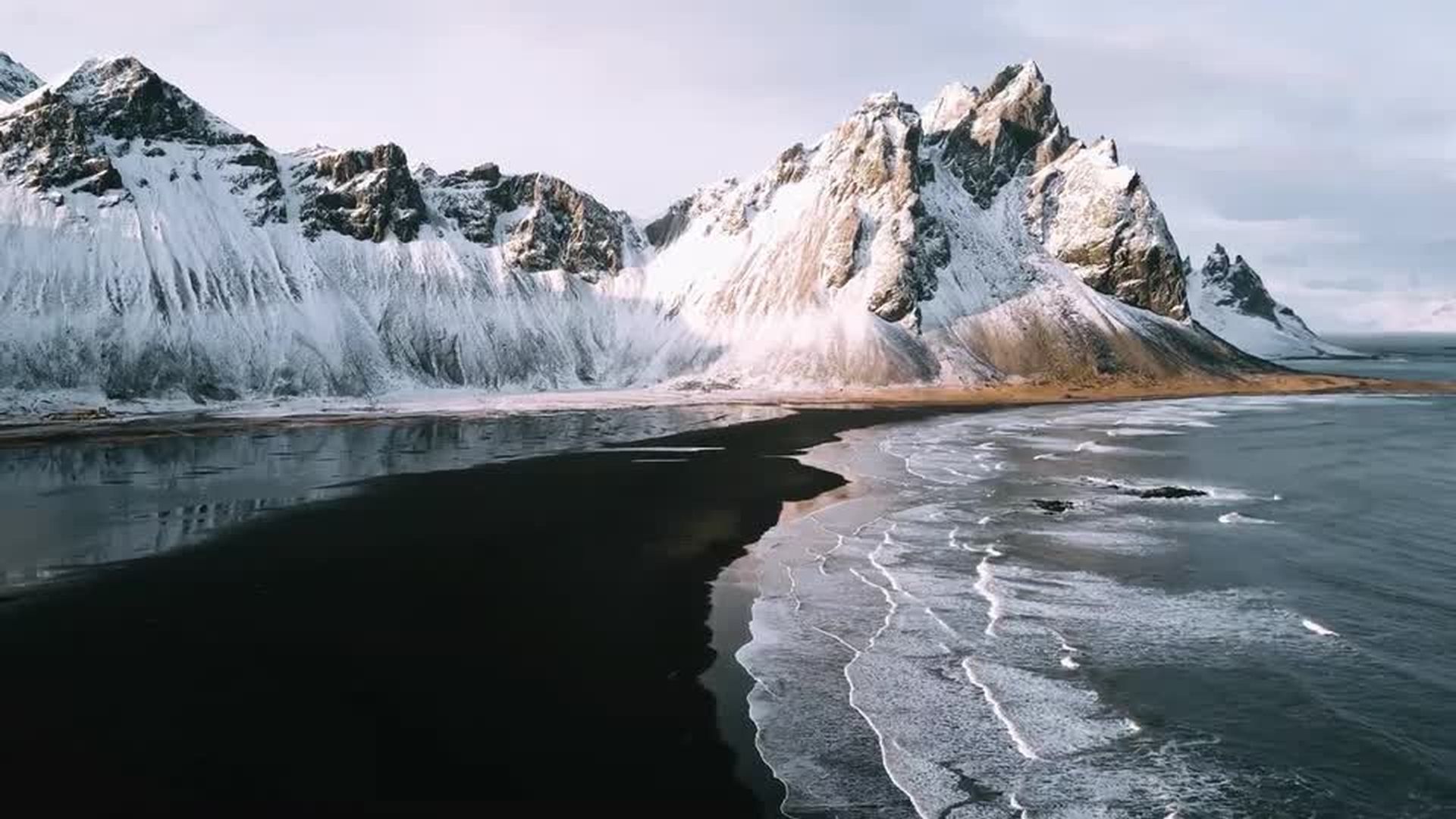
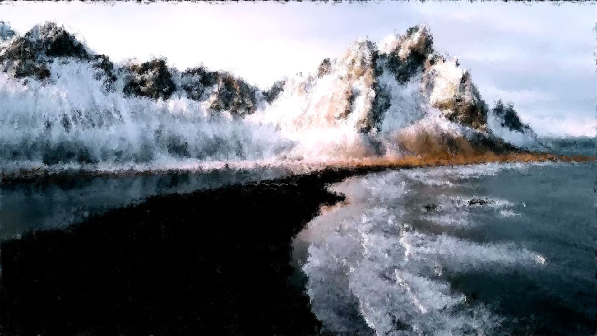
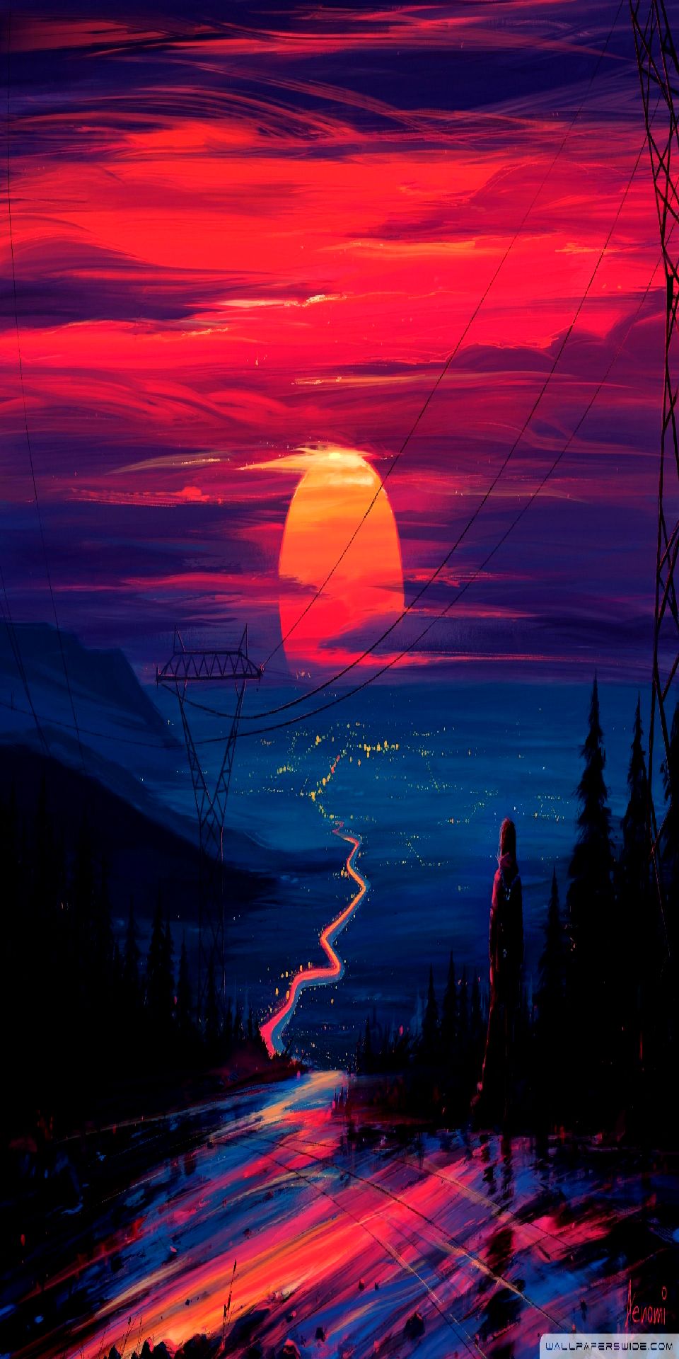
Result